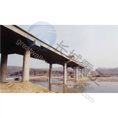
Steel Truss Bridges Can Be Divided Into Simply Supported Beam Bridges, Continuous Beam Bridges And Cantilever Beam Bridges.
Dec 01, 2021
Steel truss bridges can be divided into simply supported beam bridges, continuous beam bridges and cantilever beam bridges.
① Simply supported girder bridge: The main girder is simply supported on the pier and each hole works independently and is not affected by the displacement of the pier and abutment. The solid web main girder has a simple structure and simple design. During construction, a self-propelled bridge erector or a combined bridge erector can be used to successfully erect a single main girder at one time. However, the holes of the simply supported beam bridge are not continuous, and the vehicle will jump when passing through the crack, which will affect the speed of the vehicle. Therefore, the main beam tends to be simply supported, and the bridge deck is made continuous. As the span of a simply supported bridge increases, the internal force of the main girder will increase sharply, and the amount of materials used will increase accordingly. Therefore, the large span bridge generally does not require a simply supported beam. To
②Continuous beam bridge: The main beam is continuously supported on several piers. When the load is applied, some of the different sections of the main girder have a positive bending moment and some have a negative bending moment, and the absolute value of the bending moment is smaller than that of a simply supported beam of the same span bridge. In this way, the material consumption of the main beam can be saved. Continuous beam bridges are usually made of 3 to 5 holes in one group, there is no bridge deck joints in one group, and the driving is relatively smooth. During continuous beam bridge construction, the main beams can be erected hole by hole into simply supported beams and then connected to each other to form continuous beams. Or it can be overhanged and lengthened section by section from the pier and finally connected to become a continuous beam. In the past one to twenty years, when erecting prestressed concrete continuous beams, the jacking method was successfully used, that is, the beam body was continuously made section by section on the embankment at one end (or both ends) of the bridge, so that the construction More convenient. There are positive and negative bending moments in the main girder of a continuous beam bridge, and the structure is more complicated. In addition, the main girder of a continuous girder bridge is a statically indeterminate structure, and the uneven settlement of the piers and abutments will cause changes in the internal force of each hole of the girder. Therefore, continuous beams are generally used on bridges with better foundation conditions and larger spans. The Astoria Bridge in the United States, built in 1966, is the largest steel truss continuous girder bridge with a span of 376 meters. To
③Cantilever bridge: also known as outrigger bridge. It is a bridge with a short arm overhanging a simply supported beam to one or both ends. This type of bridge has a single cantilever bridge or a double cantilever bridge. Cantilever beam bridges often put simply supported hanging beams on the short arms, which are connected to each other to form a multi-span cantilever beam. Bridge holes with short arms and hanging beams are called cantilever holes or hanging holes, and bridge holes that support short arms are called anchor holes. The two ends of each hanging hole of the cantilever beam bridge are bridge deck joints, and the deflection of the cantilever end is also larger, and the driving conditions are not better than that of the simply supported beam bridge. The length of a main beam of a cantilever beam is longer than that of a simply supported beam of the same span, so construction and installation are correspondingly more difficult. For the prestressed concrete cantilever beam bridge, the method of cantilever assembly or cantilever pouring is often used. In order to adapt to the development of the cantilever construction method, to ensure that the internal force of the main beam is the same as during construction, there is no anchor hole, and the overhanging short arm and the pier body are directly fixed on the facade to form a prestressed concrete T-shape Rigid frame bridge, this kind of bridge was developed after the 1950s.